Limit Switch
Introduction
Limit switches serve as the mechanism that tells the computer the limits of the CNC machine. When one of the axes moves to an axis limit, the switch is activated and the machine stops. These limit switches are also use to inform the computer of the home position.
The CNC machines use limit switches to eliminate machinery vibrations, false triggers, and electrical interference between the cutting and workpieces.
Why limit Switch as End stop
For a high level of accuracy, you might want to go with an optical or magnetic endstop. However, fixing issues with these endstops could be difficult because they both use methods that are invisible to the eye. If you’re looking for the cheapest, simplest, and most-developed endstop, limit switches might be your best bet.
Limit switches or Mechanical endstops aren’t only used for axis endstops but also as bed-leveling sensors. For example, the popular BLTouch (as well as other proximity bed-leveling sensors) is essentially a mechanical endstop mounted on a hot end carriage.
These switches are used a lot in 3D printing, as seen on Creality, MakerBot, Ultimaker, Anycubic, and many other FDM printers. This technology is so commonly used because of its simple yet effective design.
Specifications:
- Price range: $1-6
- Precision: Medium
- Durability: High
- Reliability: High
- Uses: Axis endstop; bed leveling
- Pros: Very durable; reliable
- Cons: Not as precise over time as other methods
Benefits of Limit Switch
Limit switches present many essential advantages to their design:
- Designs are usually simple and easy
- Work well in almost every manufacturing setting
- Exhibit high precision and repeatability
- Are devices with power consumption
- Limit switches are reliable and rugged
- Can handle many loads at a time
- Easy to Install and maintain
Best Limit Switches for CNC
These were the best limit switches that will ensure smooth functioning of your CNC. Almost all of them work as per the two contact configurations out of which one is NC and one is NO. Apart from this, the limit switch works in the momentary action and makes it the best for CNC devices. These limit switches are functional at 250V, and upto 5A alternating current.
Here are the Best Limit Switches for CNC as far 2021
Wiring Specifications
Before starting, make sure your coordinate frame is setup properly on your CNC machine and satisfies the right-hand rule. If you’re not sure, its explained in the quick setup guide here. Otherwise, you will likely encounter problems with the homing cycle, where it behaves strangely. If you are having issues with the homing cycle, read this FAQ.
There are two types of end switches wiring
-
Normally Opened end switches (NO) - switches are connected in parallel, if the head hits one of the switches the resistance becomes low (<10 Ohm). The wiring is simple but there is no indication if one of the switches is disconnected (broken wire).
-
Normally Closed end switches (NC) - switches are connected in serial, if the head hits one of the switches the resistance become high (> 1 MOhm). The wiring is more complicated but if any of the switches is disconnected (broken wire) this will be immediately detected. This is the way how all professional CNC machines end switches were wired.
Normally-Closed (NC) vs Normally-Open (NO) switches
Use NC switches. Because whenever switches fail, the failure mode is ALWAYS “open” or “fails to make contact”. Simple fact of nature, it’s just the way things are.
Assuming a NO switch is used… While homing in on a defective switch, you will not know that the switch is malfunctioning, not until after you have crashed your machine. If the switch fails to make contact then the machine crashes.
Assuming a NC switch is used… If the switch is bad (in this case the contacts will be open), then no homing occurs, GRBL will return an error and homing does not proceed, and your machine doesn’t crash.
So it does make a BIG difference which switch contact configuration you use for limit switches, NC or NO. Crash or no crash.
Wire Routing
limit switches to Microcontroller Based Board
- The easiest way to attach limit switches to Arduino UNO is to just connect the switches to the corresponding pins and to rely on the internal weak pull up resistors (~47K) of the ATMega328 chip.
- The Normal connected (NC) switch wiring is shown below:

- The Normal Open (NO) switch wiring is shown below:

One improvement is to connect 1K to 4.7K pull up resistors to 5V and 100nF capacitors to GND. The extra pull ups and capacitors have noticeable noise suppression effect over the GRBL performance.

Capacitors for noise filtering
Even if you do use NC contacts, you still need those 104 (0.1uF) capacitors, as close to the Arduino as you can place them. You can argue all day that those caps won’t make a difference since the caps are shorted out by the switches.
The explanation for this phenomenon is quite long but the first power line glitch will convince you otherwise. (Plug in your blender next to the CNC’s AC plug and turn it on. Your CNC should still behave normally despite the blender.)
- Side benefit: With NC switches, the connection is broken cleanly when you hit home position, therefore no contact bounce occurs. (Contact bounce occurs only during switch closure, NOT during switch opening.)
Limit switches to Prallel Breakout Board
Here is the diagram for the parallel breakout board (pins 10 through 13 are used for input):
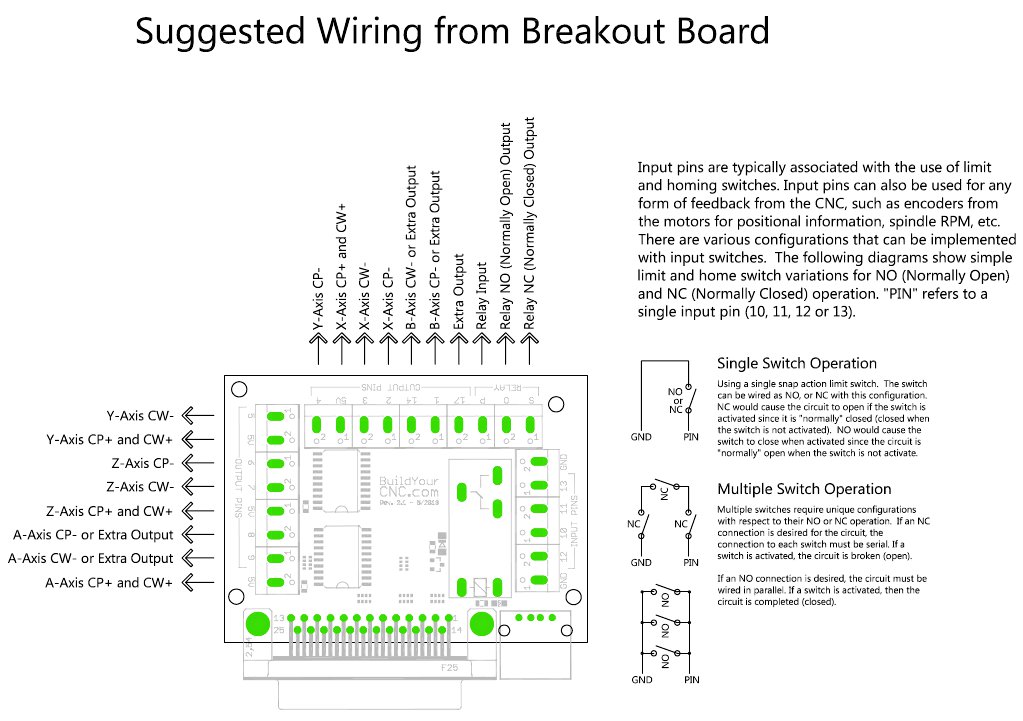
This following link will give you a certain idea of Parallel connection diagram of limit switches using 1 to 6 input ports.